X-RAY MIRROR AT ASD
 At the X-Ray Astrophysics Laboratory, we pioneered the foil approach
in X-ray imaging. For the project Suzaku , 5 telescopes were made at the
Mirror Laboratory . Each of
these telescopes consists of about 1400 conically shaped mirrors, nested in
about 175 layers and each takes the form of a quadrant of a section of a cone.
These foils will be positioned in telescope housings, and in a 2-stage
configuration which will focus x-ray at a focal length of 4.5 or 4.75 meters.
Together with a pre-collimator stage, each telescope has a diameter of about 40 cm,
and weighs approximately 20 kg.
At the X-Ray Astrophysics Laboratory, we pioneered the foil approach
in X-ray imaging. For the project Suzaku , 5 telescopes were made at the
Mirror Laboratory . Each of
these telescopes consists of about 1400 conically shaped mirrors, nested in
about 175 layers and each takes the form of a quadrant of a section of a cone.
These foils will be positioned in telescope housings, and in a 2-stage
configuration which will focus x-ray at a focal length of 4.5 or 4.75 meters.
Together with a pre-collimator stage, each telescope has a diameter of about 40 cm,
and weighs approximately 20 kg.
Telescope Design
The X-ray telescope aperture is an annulus filled with thin foil mirrors.
Mirrors are assembled in quadrants. In each quadrant, mirrors are supported
at the top and bottom edges by slotted radial bars. The slots in these
bars provide the alignment of the mirrors. In the current two stage design,
two reflections are required to bring the reflected rays to focus. In such
design, in fact, all the conical mirrors in each stage are, in fact,
confocal. The angle of incident for an axial ray on the primary (entrance)
stage is three times that on the secondary (exit) stage, for each
corresponding pair of mirror.
For the Suzaku Telescopes, the focal lengths are 4.75 m for the four XIS
system and 4.50 m for the XRS system. The plate scales are 0.72 and 0.76
arc-min/mm, respectively.
Suzaku X-Ray Telescope design parameters are listed in the table below.
Those of ASCA Telescopes are also
given for reference.
X-Ray Telescope Design Parameters
| |
Suzaku XIS |
Suzaku XRS |
ASCA XRS |
| Focal Length (m) |
4.75 |
4.50 |
3.50 |
| Number of Telescope |
4 |
1 |
4 |
| Mirror Substrate |
Aluminum |
Aluminum |
Aluminum |
| Substrate Thickness (micrometer) |
155 |
155 |
127 |
| Reflecting Surface |
Au |
Au/Pt |
Au |
| Au thickness (Angstrom) |
2000 |
2000 |
500 |
| Other structure |
Epoxy coupling layer |
Epoxy coupling layer |
Acrylic lacquer finish |
| |
25 um |
25 um |
10 um |
| Inner Diameter (mm) |
118 |
119 |
120 |
| Outer Diameter (mm) |
399 |
400 |
345 |
| Mirror Length (mm) |
101.6 |
101.6 |
100 |
| Number of Nestings |
175 |
168 |
120 |
| Foil / Telescope |
1400 |
1344 |
960 |
| Primary incident angle (degree) |
0.18 - 0.60 |
0.19 - 0.63 |
0.24 - 0.70 |
| Pre-collimator |
Yes |
Yes |
No |
| Weight / Telescope (kg) |
16 |
16 |
9.84 |
| Geometric Area / Telescope (cm2) |
873 |
887 |
558 |
| Field of View at 1 keV (arc-min) |
19 |
19 |
24 |
| Field of View at 7 keV (arc-min) |
19 |
19 |
16 |
Mirror Fabrication at ASD
Each foil mirror is composed of an alumiumum substrate, a smooth metallic
surface which is responsible for the reflection of x-ray at grazing incidence, and
a layer of epoxy which serves to bond the reflecting surface to the substrate.
The light-weight aluminum substrate is 155 micrometer thick, providing most of
the mechanical strength of the mirror as well as the proper shape. The metallic
surface for x-ray reflection is a thin layer of gold or platinum.
The high (electron)
density of these material provides excellent reflection of x-ray at small angle of
incidence. The epoxy layer bonding the gold layer and the aluminum foil is
approximately 25 micrometer thick.
The fabrication of such mirror consists of the following processes:
- Preparation of flat aluminum foil from sheets.
 Sections of circular arc are cut from flat aluminum sheets.
With the
present 2-stage design, the inner and outer radii of curvature
are the same for each flat foils of a particular stage.
Different arc lengths of the same circular annulus (one of each
stage) are cut in order to make mirrors of different nesting radii.
These foils
are treated and cleaned to remove surface contamination as well as
boundary distortion.
Sections of circular arc are cut from flat aluminum sheets.
With the
present 2-stage design, the inner and outer radii of curvature
are the same for each flat foils of a particular stage.
Different arc lengths of the same circular annulus (one of each
stage) are cut in order to make mirrors of different nesting radii.
These foils
are treated and cleaned to remove surface contamination as well as
boundary distortion.
- Forming of flat aluminum foil into conical sections.
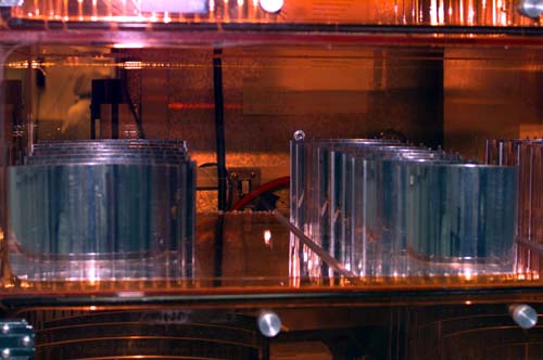 Flat foils are rolled machincally into approximate conical shapes,
again, different radii for different nesting position.
A number of them are stacked together and are placed against a
conical mandrel of matching dimension. The stack is sealed and
the volume containing the foil is evaluated, thus allowing
atmospheric pressure to act on the foils. The foils are then
heat-formed, and they subsequently take the precise
shape of the parent mandrel.
Flat foils are rolled machincally into approximate conical shapes,
again, different radii for different nesting position.
A number of them are stacked together and are placed against a
conical mandrel of matching dimension. The stack is sealed and
the volume containing the foil is evaluated, thus allowing
atmospheric pressure to act on the foils. The foils are then
heat-formed, and they subsequently take the precise
shape of the parent mandrel.
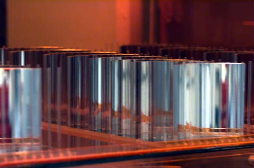
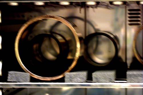
- Sputter thin layer of gold onto glass mandrels.
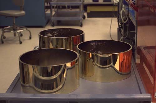 Films of gold or platinum, of about 2000 Angstroms, are coated on
glass mandrels by sputtering. The glass mandrels are cylinders
15 cm in height in order to accomodate the 10 cm width foils.
These mandrels are glass which has a very smooth surface
with roughness of a few angstroms over scales of mm. These glass mandrels are
used for surface replication.
Films of gold or platinum, of about 2000 Angstroms, are coated on
glass mandrels by sputtering. The glass mandrels are cylinders
15 cm in height in order to accomodate the 10 cm width foils.
These mandrels are glass which has a very smooth surface
with roughness of a few angstroms over scales of mm. These glass mandrels are
used for surface replication.
- Coupling of the aluminum foil with the gold-coated glass mandrel.
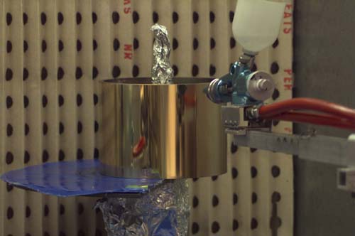 Small amount of liquid epoxy is sprayed onto the conically shaped
foils as well as gold-coated replicating glass mandrels.
A thin layer of epoxy is desirable in order to reduce mismatch of
thermal expansions between the epoxy and the
aluminum substrate.
Small amount of liquid epoxy is sprayed onto the conically shaped
foils as well as gold-coated replicating glass mandrels.
A thin layer of epoxy is desirable in order to reduce mismatch of
thermal expansions between the epoxy and the
aluminum substrate.
 A foil and a mandrel, with wet epoxy on them, are coupled together
in vacuum in order to avoid trapping any air. The liquid epoxy also
serve as a mild buffer for the mating the glass and the aluminum.
A foil and a mandrel, with wet epoxy on them, are coupled together
in vacuum in order to avoid trapping any air. The liquid epoxy also
serve as a mild buffer for the mating the glass and the aluminum.
 Coupled foil-mandrels are now placed in oven for epoxy curing.
- Removal of replicated foils from mandrels.
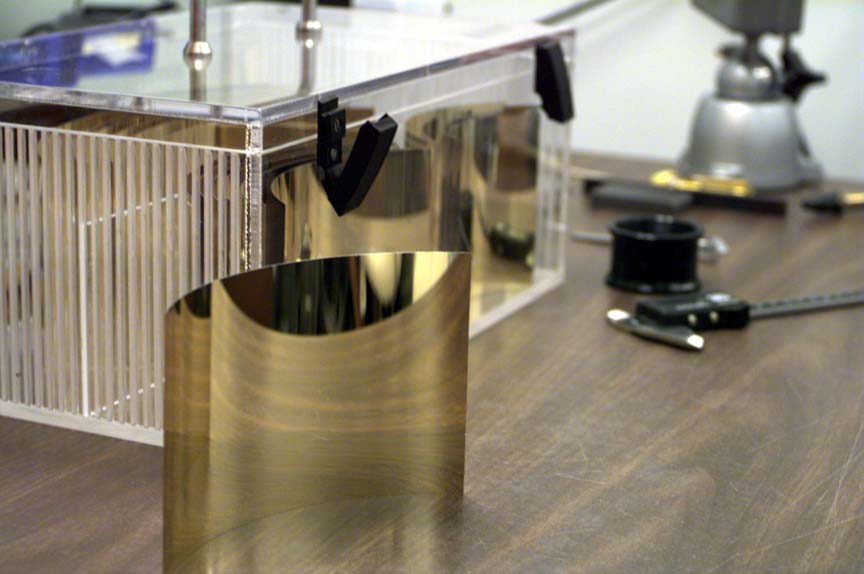 The foil can be removed from the glass mandrels after the epoxy
is cured. The removal is possible due to the non-sticking nature
of gold on glass. The foil, now with the gold layer on it, acquires
the smoothness of the glass.
The foil can be removed from the glass mandrels after the epoxy
is cured. The removal is possible due to the non-sticking nature
of gold on glass. The foil, now with the gold layer on it, acquires
the smoothness of the glass.
Replicated Surfaces and Metrology
Replicated foils are examined with optical means before further tests are made in the x-ray.
Examinations are performed to check the quality of both the mirror configurations as
well as surface roughness.
- Visual Examination.
Visual Examination by naked eyes are the preliminary checks for gross mal-replication.
- Image of a Stand-alone Foil.
The focussing characteristics of each individual foil is examined using a uniform
parallel beam of white light.
- Surface Roughness under a microscope.
Larger scale surface roughness can be discerned under a microscope. Depending
on the magnification of the microscope, surface feature of lateral scale of
a mircron to a millimeter can be examined.
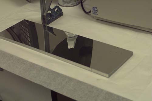
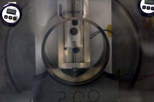
- Waviness and surface roughness with a laser scan micrometer.
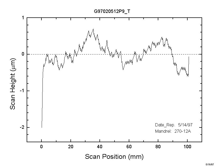 A laser scan mircrometer with linear and rotational travel is used to examine
both the surface waviness and roughness. The lateral length scale is limited
by the range of the travelling stage. In the present set up, the scanning can
be done over a range of more than 20 cm, with a resolution of approximately
30 micron, primarily limited by the size of the laser beam. The
depth of the scan has a resolution of 0.1 micron. A typical session of a linear
scan is shown (left).
A laser scan mircrometer with linear and rotational travel is used to examine
both the surface waviness and roughness. The lateral length scale is limited
by the range of the travelling stage. In the present set up, the scanning can
be done over a range of more than 20 cm, with a resolution of approximately
30 micron, primarily limited by the size of the laser beam. The
depth of the scan has a resolution of 0.1 micron. A typical session of a linear
scan is shown (left).
- Surface roughness with an optical interferometric profiler.
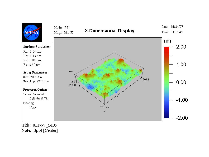 Finer details of surface characteristics can be more efficiently resolved with
an optical interferometric profiler. Such profiler provides 2D and 3D display
and analysis. The lateral resolution is better than a micron at high magnification,
with a depth resolution of about 0.5 Angstrom. Roughness at the sub-nanometer
range is important for x-ray reflectivity. A Typical scan of a gold-coated foil
is shown.
Finer details of surface characteristics can be more efficiently resolved with
an optical interferometric profiler. Such profiler provides 2D and 3D display
and analysis. The lateral resolution is better than a micron at high magnification,
with a depth resolution of about 0.5 Angstrom. Roughness at the sub-nanometer
range is important for x-ray reflectivity. A Typical scan of a gold-coated foil
is shown.
- Surface microroughness with a scanning probe microscope.
Roughness at sub-micron scale is measured with an atomic force microscope.
|