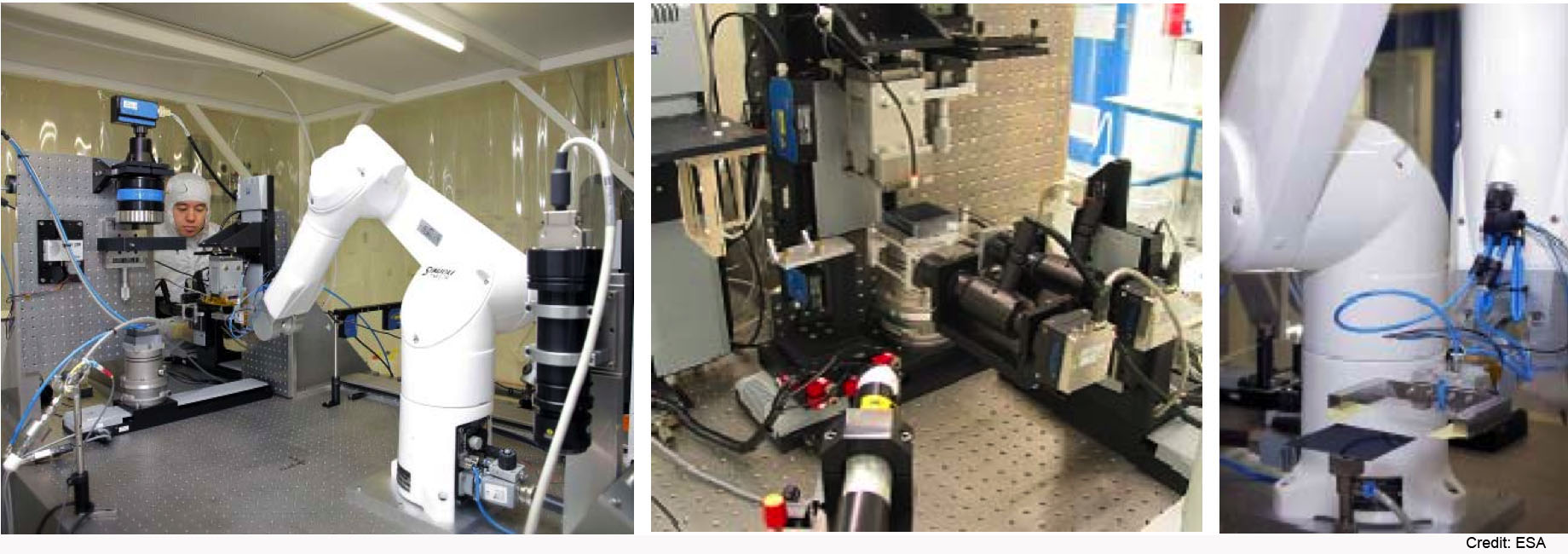
 |
Goddard Space
Flight Center NASA > GSFC > Astrophysics Science Division > IXO |
|

You are here: Technology» Recent Technology Milestones»
These are highlights of recent developments from some of the IXO instrument technology teams.
Date: February 2011
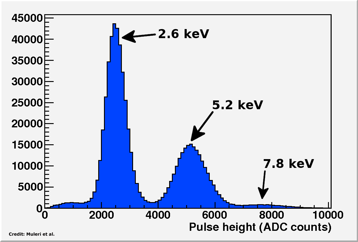
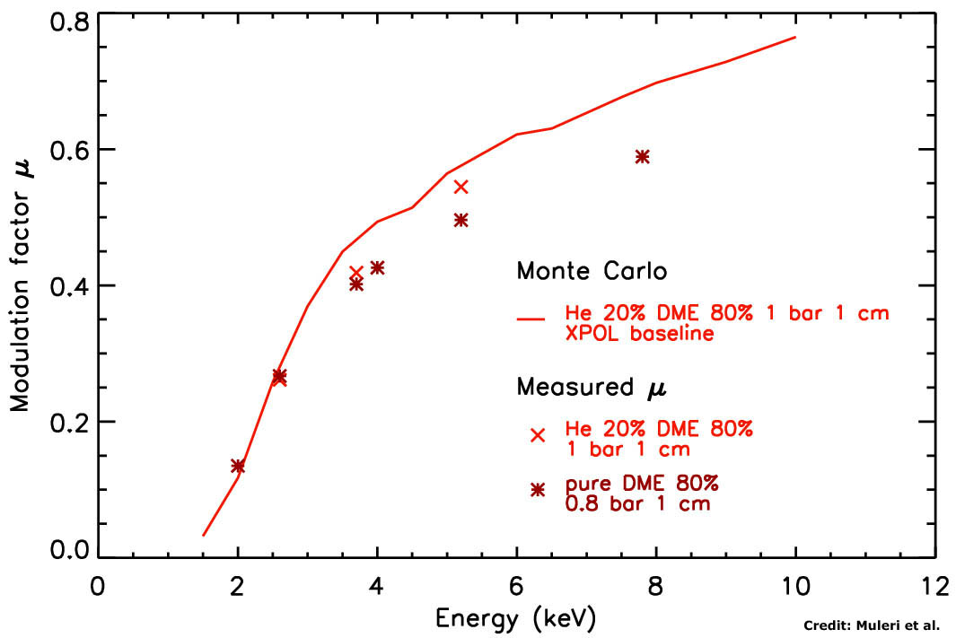
The XPOL team is continuing to investigate how different gas mixtures impact on the sensitivity of the X-ray polarimeter on-board of IXO. The choice of the mixture in which X-ray photons are absorbed and photoelectrons propagate deeply affects both the energy range of the instrument and its performance in terms of gain, track dimension and, ultimately, polarimetric sensitivity. Recently, a mixture of pure Dimethyl Ether (DME) at 0.8 bar, selected for its very low diffusion coefficient, was tested at the X-ray calibration facility at INAF/IASF-Rome with polarized and monochromatic radiation. The modulation factor and the energy resolution were measured at 2.0—7.8 keV, which completely covers the energy range of the instrument. Expectations on polarimetric sensitivity at low energy of 2.0 keV, where it has its peak sensitivity, were completely confirmed. The modulation factor at 2.0 keV, which is the low energy threshold, is 13.5%. The energy resolution is 24% at 6 keV, which is very close to the goal value of 20% at 6 keV.
|
|
|
Spectrum of monochromatic photons at 2.6, 5.2 and 7.8 keV. The energy resolution is 32.1% at 2.6 keV, 24.5% at 5.2 keV and 23.5% at 7.8 keV (Muleri et al., 2010). Click the image for a larger view |
Measured modulation factor for two mixtures compared to the expected results calculated with Monte Carlo simulations. The blue circles are the measured values for the XPOL baseline (Helium 20% and DME 80% at 1 bar), while the red diamonds are the measured values for pure DME at 0.8 bar. The solid black line is the expected dependence for DME at 0.8 bar (Muleri et al., 2008; Muleri et al., 2010). Click the image for a larger view |
|
|
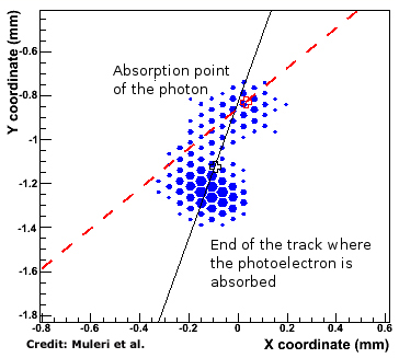
Examples of a real track at 5.2 keV in pure DME. The reconstructed direction of photoelectron emission obtained by analyzing the entire track and resolving the first part are the black solid line and the red dashed one, respectively. Thanks to the high spatial resolution of the Gas Pixel Detectors (GPD), the latter is by far a best estimate of the direction of emission. The barycenter of the charge distribution and the impact point, which is the best estimate of the absorption point of the photon, are the black and the red crosses respectively (Muleri et al., 2010). Click the image for a larger view |
References:
Date: November 2010
The mirror technology development team at GSFC produced mirror substrates with 4.5" HPD (two reflection equivalent) figure, breaking the 5" HPD barrier. This number is to be compared with the IXO requirement of 3.2" HPD. The team successfully demonstrated that it could repeatedly attach mirror segments to strongbacks, over-constraining them without degrading their figure. This is a significant step toward aligning and permanently bonding mirror segments into module housing. The team members have been able successfully align, transfer, and permanently bond a parabola and hyperbola pair onto a mirror housing simulator. When placed in an x-ray beam, mirror segments generated x-ray images as good as 9.7" HPD at 4.5 keV, breaking the 10" HPD barrier for aligned and bonded mirror pairs.
Date: August 2010
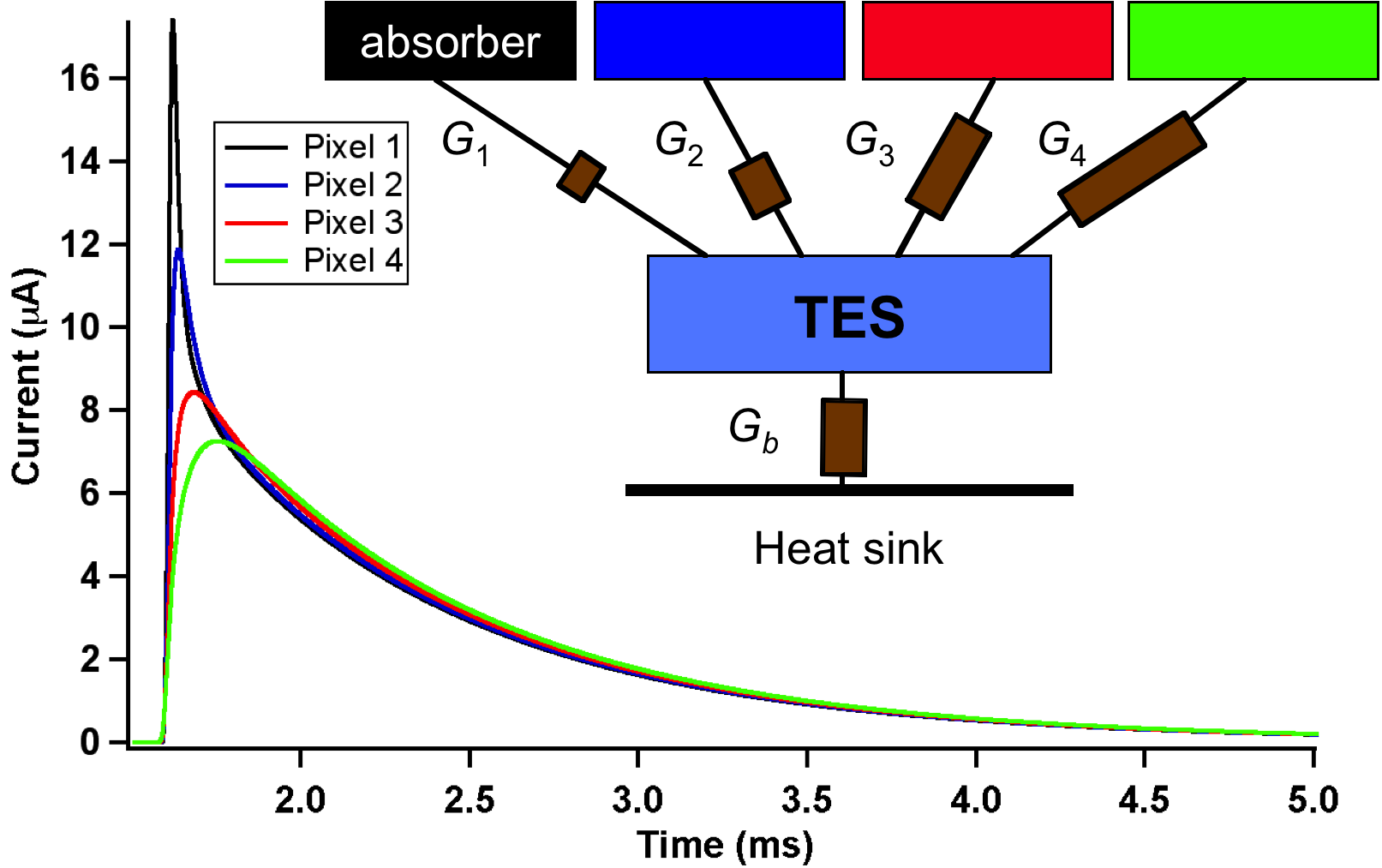
The GSFC XMS team is developing several transition-edge sensor (TES) detector approaches for the XMS extended focal-plane array. This 52 × 52 array (2304 elements surrounding the core) of 600 μm pitch pixels will increase the XMS field-of-view from 2´ to 5.4´ with a resolution of 10 eV. However, significantly increasing the number of readout channels is unfavorable due to the increase in mass and power of the readout chain as well as adding complexity in the focal-plane design.
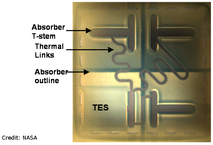
Optical micrograph looking through the Si-N membrane at the back of a 4-pixel 250 μm pitch Hydra. Each absorber is cantilevered above the membrane using a T-shaped attachment stem. Credit: NASA/GSFC. Click the image for a larger view
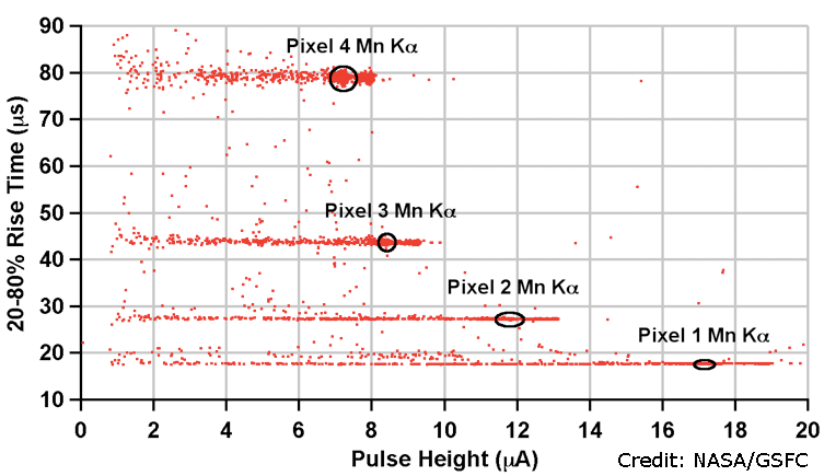
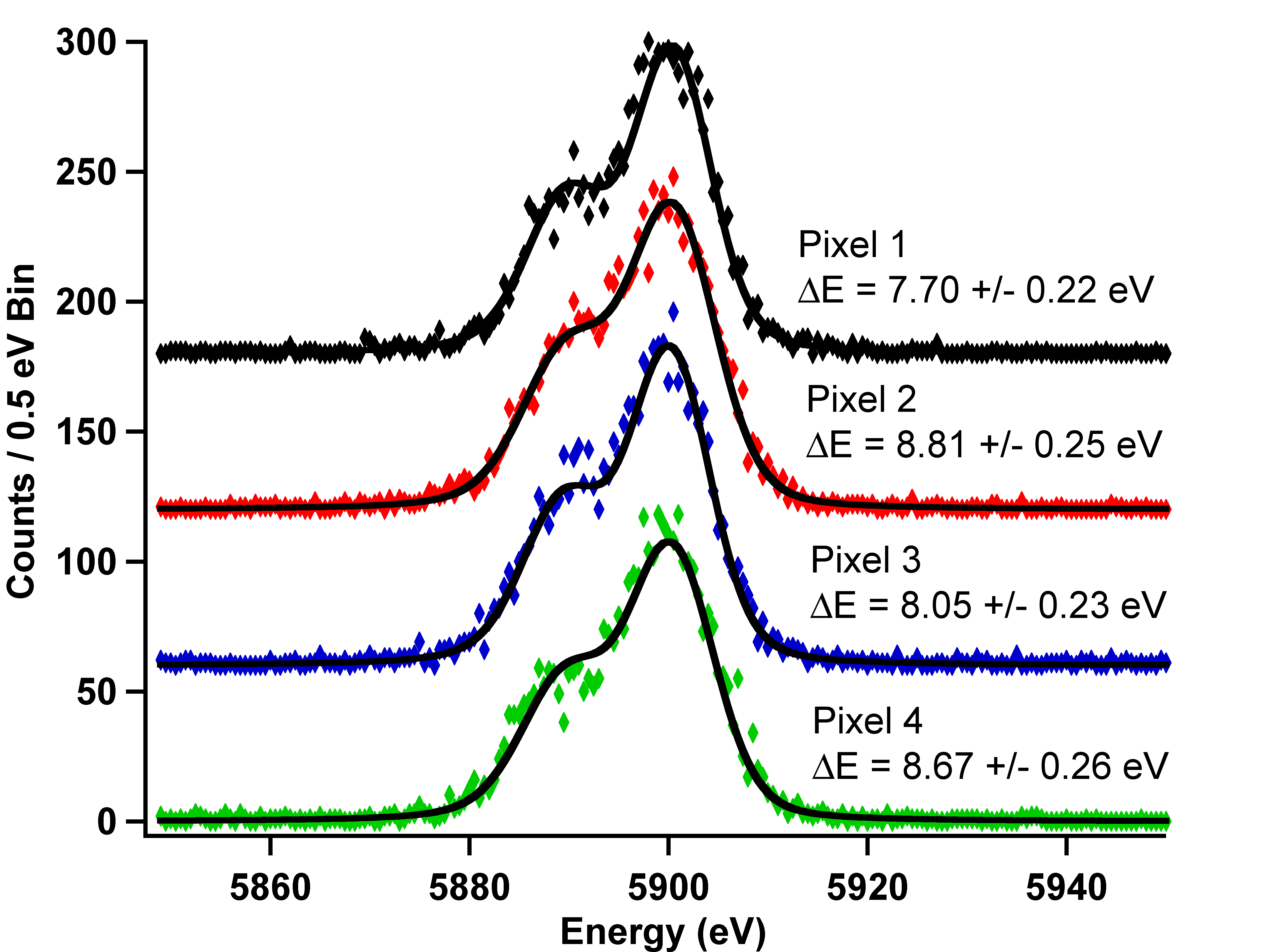
One approach the team is investigating is "Hydra" devices, which consist of four discrete absorbers each with a different metallic thermal link to a single readout TES. See the figure on your right. Careful tuning of each thermal conductance of each link results in a different characteristic pulse shape corresponding to each Hydra absorber. Position information is then found from the pulse shape. Hydras are designed to enable maximum field-of-view with the least number of additional read-out channels and are ideally suited for the XMS extended array. First results on prototype Hydras with 250 μm pixel pitch demonstrated an energy resolution of 5—6 eV across all four pixels at an energy of 6 keV. Position discrimination was determined from pulse height vs rise time data, as shown in the figure below. The team is now fabricating similar Hydra devices on the required IXO plate scale of 600 μm. This will increase the XMS field-of-view from 2´ to 5.4´ with an energy resolution of < 10 eV.
|
|
|
Average Mn-Kα pulse shapes for typical Hydra. After the initial position-dependent equilibration signal the pulses decay with the same exponential rate. The inset shows a simple thermal model of the Hydra concept including four absorbers with different thermal couplings to a TES, which is in turn weakly thermally coupled to a heat sink. Credit: NASA/GSFC. Click the image for a larger view |
Raw pulse height vs. rise time for a typical Hydra, which enables position discrimination between pixels. The Mn-Kα regions are circled for each absorber pixel. Credit: NASA/GSFC. Click the image for a larger view |
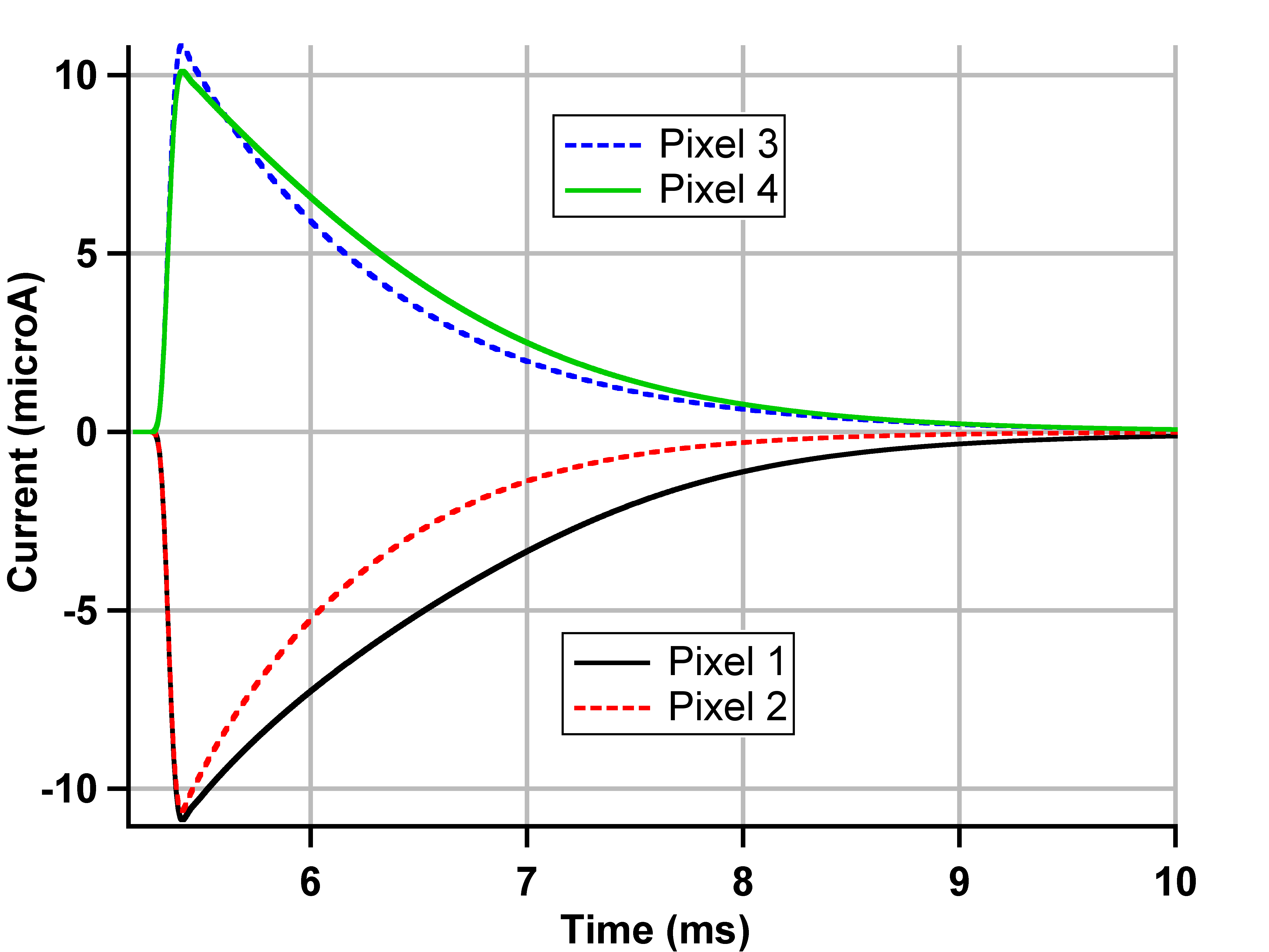
Another approach is to inductively couple 4 pixels to a single SQUID read-out. Since the SQUID measures the total noise from all 4 TES, the energy resolution is degraded by 2 times, but the benefit comes from the reduction in the number of electronic readout channels by 4 times. Position discrimination between the pixels is made possible by combining detectors with different inductive couplings and also due to intrinsic detector design parameters where each pixel has a different characteristic pulse shape, see the figure below. In a proof-of-concept test, the team has demonstrated an energy resolution of < 9 eV across four 500 μm pixels inductively coupled to a single SQUID. Straightforward position discrimination from pulse shape analysis was demonstrated at a photon energy of 6 keV. When read-out individually, the best-achieved resolution was ~ 3.5 eV. Further improvements in resolution are predicted for fully optimized devices and future tests are planned for pixels with the full 600 μm plate scale.
|
|
|
Mn-Kα spectrum from an 55Fe x-ray source for 4 500 μm single pixel devices inductively coupled to a 2-stage PTB SQUID. Each spectrum is vertically offset by 60 counts. Credit: NASA/GSFC. Click the image for a larger view |
Average measured Mn-Kα pulse shape data for 4 500 μm pixels coupled to a 2-stage PTB SQUID. Pixels 3 and 4 have positive bias polarity and pixels 1 and 2 have negative bias. Pixels 2 and 3 had ~ 2 times stronger thermal coupling to the heat sink than pixels 1 and 4. Thus, there are 4 discrete pulse shapes. Credit: NASA/GSFC. Click the image for a larger view |
References:
Date: July 2010
The Segmented Glass mirror team continues to make progress toward TRL-6. Recently, the Segmented Glass mirror team at GSFC has demonstrated that it can over-constrain mirror segments without distorting their optical figure. The team members have been able to bond a mirror segment at six locations to a strongback, effectively converting the flexible mirror segment into a rigid body that can be positioned and oriented using traditional alignment equipment and facility. The team achieved consistency and repeatability in mirror segment bonding for a single mirror segment, as well as for different mirror segments. This is a significant and necessary step toward installing, aligning, and bonding the 15,000 or so mirror segments required by IXO. In the next few months, the team will perform detailed measurement to quantify and automate the process so that it can eventually become a part of a mass production process for making the IXO flight mirror assembly.

Mirror segment bonding using four totally independent trials. In each case, the mirror segment was measured for its "free-standing" figure (left) and bonded to the strongback (right). Credit Will Zhang, NASA/GSFC. Click the image for a larger view
Date: May 2010
IXO has now been the subject of four independent system studies: in the ESA Concurrent Design Facility (CDF), the NASA Mission Design Lab (MDL) and two ongoing industrial studies by Thales Alenia Space and Astrium UK, commissioned by ESA as part of the Cosmic Vision Phase A. All indicate that the mission is feasible with no "show stoppers" identified. The NASA design meets the science requirements, with adequate margins. The ESA-sponsored industry studies are being carried out to meet the very stringent margins that were mandated for the selection of L-class missions. These studies will be completed by July 2010, and will increase further the mission’s level of definition. Read more ...
Date: April 2010
The HTRS is currently terminating its assessment study phase. The study is led by an integrated team from Centre d´Etude Spatiale des Rayonnements (CESR) and Centre National d´Etudes Spatiales (CNES) in Toulouse (France). The study involves an international consortium, including contributions from Germany, Switzerland, Italy and the Netherlands. The main HTRS requirements for neutron star and stellar mass black hole science (equation of state of matter at supra-nuclear densities, black hole spins and strong gravity probes) is to handle a source with the Crab intensity with deadtime and pile-up less than 2%. To match this requirement, in its current design, the HTRS is an array of 31 SDDs, placed slightly out of focus, in such a way that the focal beam is spread quasi-uniformly over the array. This solution maximizes the performance of the instrument, by increasing its count rate capability.
Along the study phase, the electrical, mechanical and thermal design of the instrument was consolidated. The HTRS is made of two main components: the focal plane assembly (which includes the filter wheel), and the digital electronics, which is divided in two parts: the so-called Pre-Processing Units (PPU, which takes the output of the FEE analog chain), and the Data Processing Unit (DPU, whose main functions are the packaging of the science data and the instrument management). The detector unit includes the detector hybrid, the readout FEE ASIC hybrid and the flex interconnections. The SDD array is protected from radiations through a proton shield. The detector will be passively cooled and regulated at -40ºC. The focal plane assembly includes the shielded detector unit, the filter wheel and the support structure. The assembly is surrounded by connectors going directly to the electronics box located less than 1 meter away. The filter wheel will have 5 positions (close, open, 2 optical filters, calibration source). It will consist on a single motor operated by two commands (2 coils). The gears and the motor is enclosed to prevent contamination on the cold SDD array. The mass and power budgets of the instrument was also consolidated to be 30.3 kg (with 20% margins) and a peak consumption power of 175 W (with 70% DC-DC conversion efficiency and 20% margins).
To conclude, the HTRS relies on existing technologies, which all have a high technology readiness level. Its current HTRS design meets the top level IXO requirements (<10 % deadtime @ 1 Crab) with very safe margins. No issues were raised during the mid term review conducted by ESA (end of March 2010). The mass and power budgets were consolidated and remained within previous allocations.
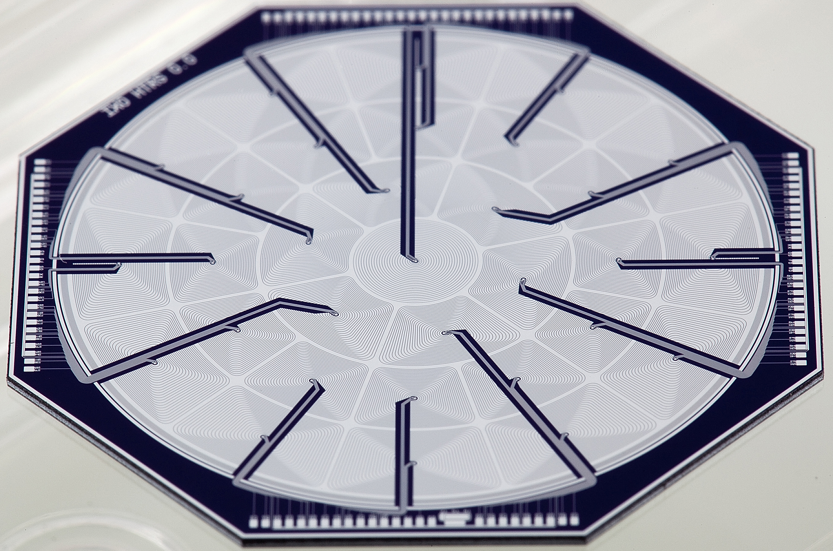
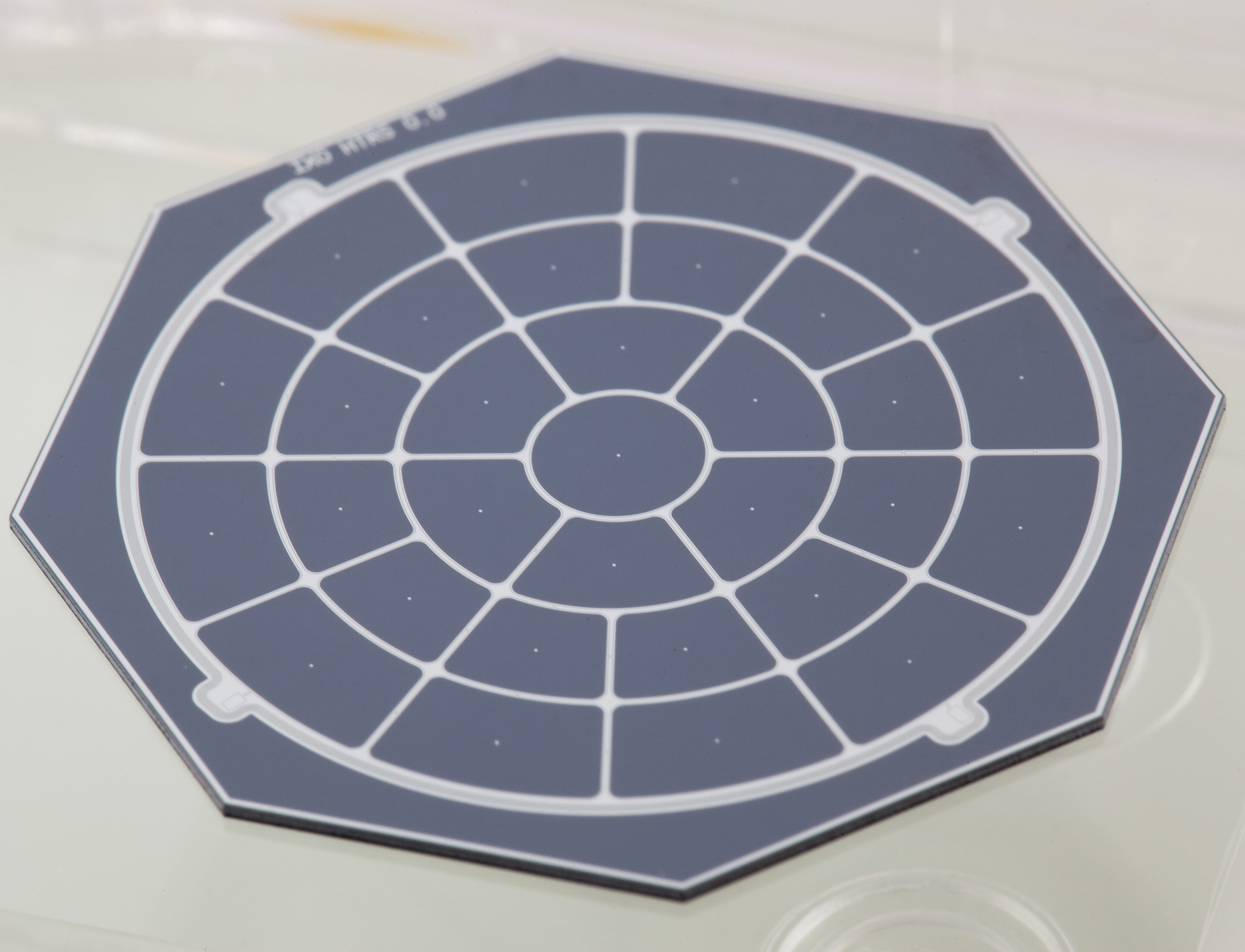
HTRS design on a dummy wafer, with the 31 SDDs clearly visible. The images show the entrance window and the back side of the array. Courtesy of Peter Lechner. Click the image for a larger view
Date: April 2010
The Segmented Glass Mirror Technology team has been making steady progress in the last year. It has completed the fabrication of a second pair of forming mandrels that meet the IXO requirement of 2.5" HPD (two reflections). On the mirror fabrication front, the team has achieved the 7.5" HPD (two reflections) level for mirror segments, which is dominated by the forming mandrel figure quality. Once the new forming mandrels are used, by the end of this year, the team expects to make mirror segments at the 5" HPD level or even better. There also continues to be progress in mounting and aligning mirror segments at both GSFC and SAO. The team just has successfully bonded mirror segments to structures simulating module housings.
A recently completed mirror-housing simulator at GSFC – four independent displacement sensors have been installed to monitor the alignment and bonding of mirror segments. A smart-bonding technique using these displacement sensors has achieved a bonding repeatability of better than 100nm, which even beats IXO requirements. Credit GSFC
Date: September 2009
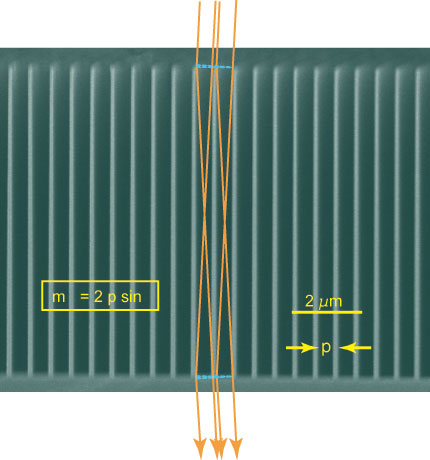
The Space Nanotechnology Laboratory at MIT's Kavli Institute for Astrophysics and Space Research is progressing with the next generation of CAT gratings. Since their initial successful X-ray demonstrations of the CAT grating concept with large-period and lower aspect-ratio prototypes, the lab has now microfabricated 200 nm-period silicon CAT gratings comprised of grating bars with 6 micron depth, optimized for the 0.3 to 1.0 keV energy band. Preliminary analysis of recent X-ray tests has shown blazing behavior up to 1.28 keV in accordance with predictions.
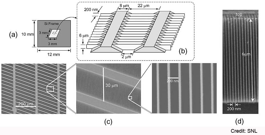
Fabrication results. (a) Schematic top view of a CAT grating sample. (b) Schematic (not to scale) of CAT grating bars (white) and level I support mesh (gray). (c) Top view SEM images from sample S6B at various magnifications, showing level I support grid and CAT grating bars. (d) SEM image of cleaved cross section from sample S6A, showing the high aspect ratio of the CAT grating bars. Credit: SNL. Click the image for a larger view
Additional Links
+ SPIE proceedings paperDate: September 9, 2009
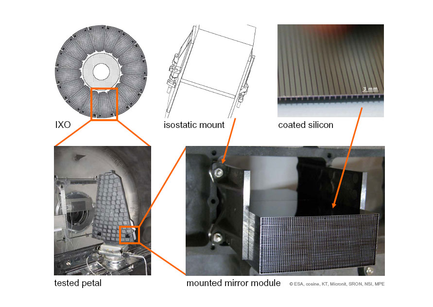
The international consortium for developing Silicon Pore Optics (SPO) is making a steady progress. Recently, they have developed the next generation of the automated stacking robots. Using this robot they have built stacks with wedged plates and measured them at the BESSY synchrotron radiation facility. The stacks achieved in single reflection a half-energy width (HEW) of 7" on the first nine plates, which corresponds for a mirror module in double reflection to 10". This compares to 17" on the first four unwedged plates measured in 2007 and demonstrates the significant improvement in stacking quality. The complete first plate exhibits in single reflection a HEW of 4.2".
Stacking robot inside the class 100 clean area at cosine. The system is installed on a vibration isolated table and consists of more than 16 axes. It is fully automated and is designed to build stacks up to 100 plates high. The plates can be positioned with μm accuracy and automatically be bent into the required shape. Credit: ESA. Click the image for a larger view.
In parallel, the SPO team has developed and demonstrated stacks with patterned iridium coatings with carbon overcoatings inside the pores. The team has successfully performed the first pull tests and is now preparing environmental tests. New wedging techniques have been developed that allow meeting the requirements of IXO and methods been explored to overcome the performance limits imposed by the conical approximation.
Also, the technological issues of cleanliness and bonding have been addressed by improved assembly hardware developed in the course of the ongoing technology research program and by the steep learning curve in assembling pore optics. So far, no issue has been identified that would impede improving the performance of silicon pore optics beyond 5".
Additional Links
+ Stacking of Silicon Pore Optics for IXODate: May 2009
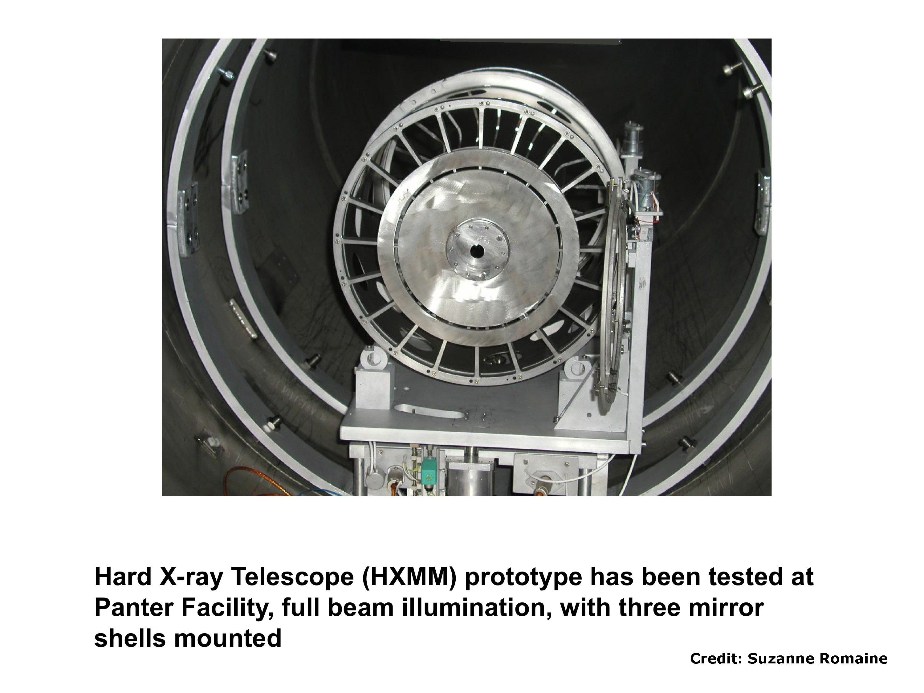
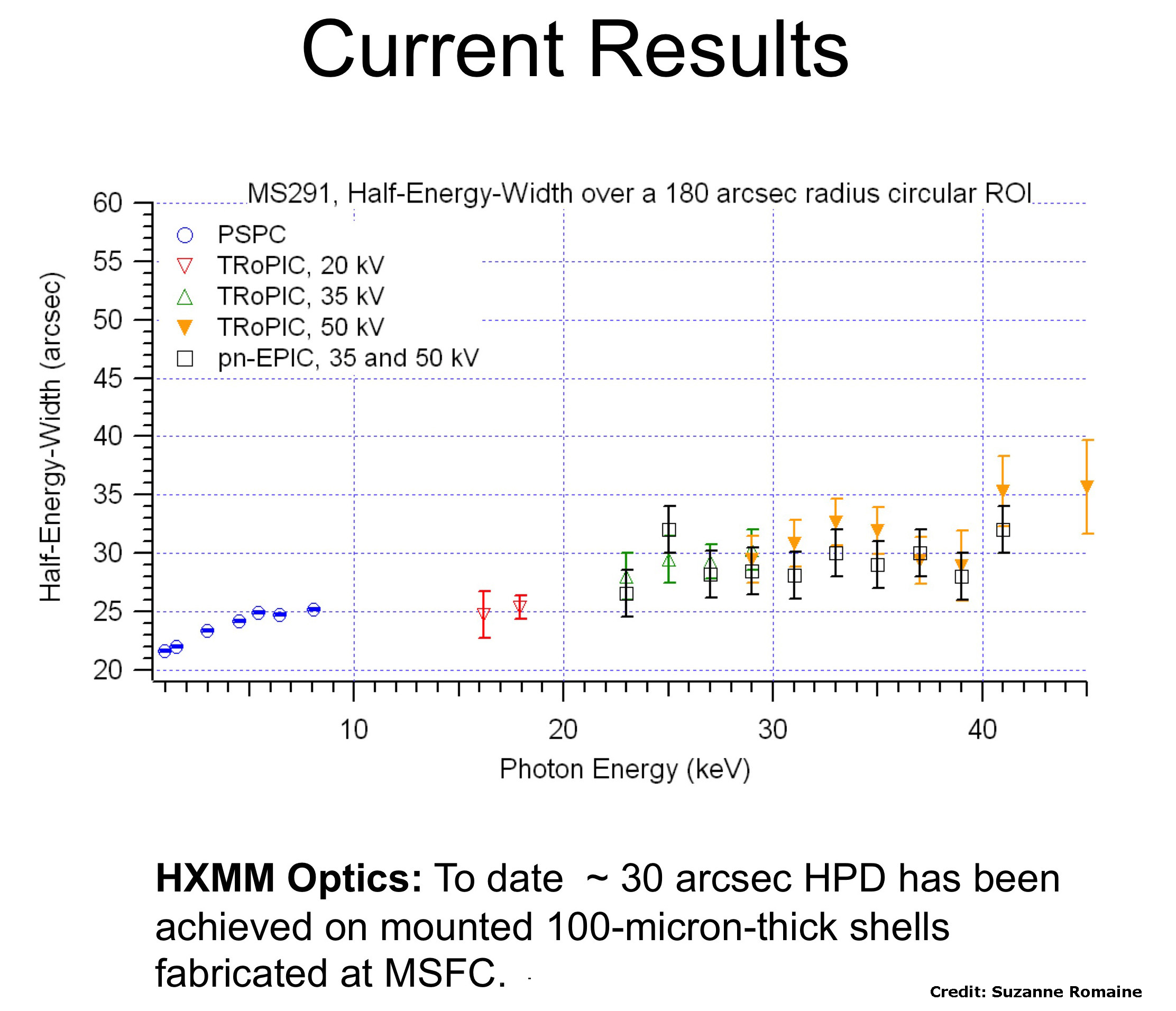
Hard X-ray Telescope (HXMM) prototype has been tested at the PANTER Facility using the full beam illumination, with three electroformed nickel replication (ENR) mirror shells mounted. Up-to-date, ~ 30 arcsec HPD has been achieved on mounted 100-micron-thick nickel shells fabricated at MSFC.
|
|
|
Hard X-ray Telescope (HXMM) prototype has been tested at Panter Facility, full beam illumination, with three mirror shells mounted. Credit: Suzanne Romaine. Click the image for a larger view. |
HXMM Optics: about 30 arcsec HPD has been achieved on mounted 100-micron-thick shells fabricated at MSFC. Credit: Suzanne Romaine. Click the image for a larger view. |
Date: April 2009
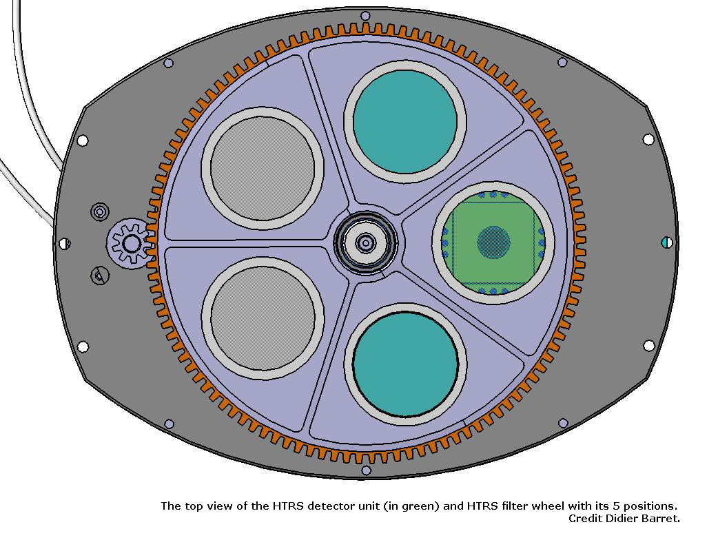
The Centre d´Etude Spatiale des Rayonnements has completed the description of the HTRS in the IXO Payload Definition Document. The instrument is based on an array of Silicon Drift Detectors (SDD), manufactured by the The Max-Planck-Institut Halbleiterlabor. The University of Geneva has designed the filter wheel for the HTRS. The filter wheel is a system to protect the detector, and to reduce the optical loading on the SDD array. It consists of a rotating disk perpendicular to the optical beam and controlled by a motor. The motor is commanded by a dedicated electronics, which allows us to select accurately a specific orientation of the filter wheel.
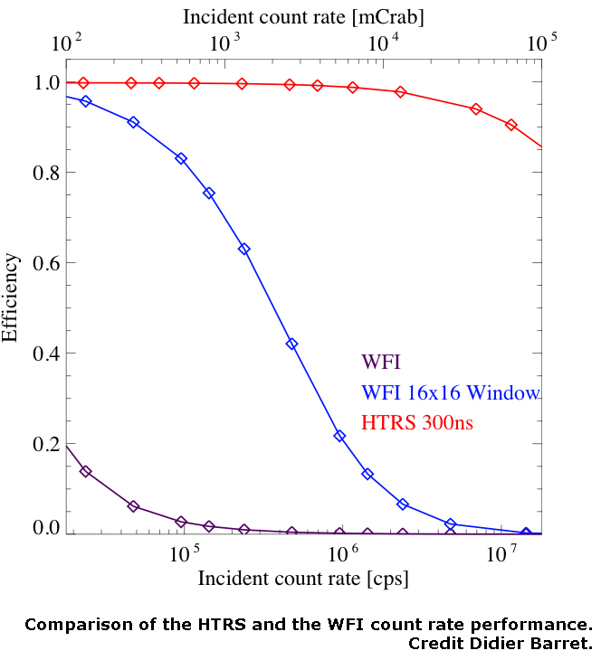
In parallel, the University of Tübingen and the University of Erlangen-Nuremberg have performed Monte Carlo simulations to estimate the loss of efficiency of the HTRS caused by to deadtime. The simulations assume a point source illuminating the SDD array located at an out of focus distance of 12 cm for 4 mm hexagonal pixel size. The source was assumed to have a constant count rate and a Crab-like spectrum. Photon arrival times onto the HTRS are generated according to Poisson statistics. The deadtime and energy pile-up are taken into account by discarding photons hitting a pixel within 300 ns of the previous photon. The loss of efficiency due to deadtime and pile-up is negligible up to about 10 times the intensity of the Crab.
|
|
|
The top view of the HTRS detector unit (in green) and HTRS filter wheel with its 5 positions. Credit: Didier Barret. Click the image for a larger view. |
Comparison of the HTRS and the WFI count rate performance as a function of the incident count rate. The estimates for the WFI are computed for a standard mode and for the fastest window mode. The loss of efficiency due to deadtime and pile-up is negligible up to about 10 times the intensity of the Crab. Credit: Didier Barret. Click the image for a larger view. |
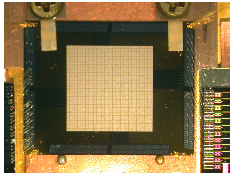
Photograph of 32x32 array of TES pixels on 0.3 mm pitch. Click the image for a larger view.
Date: March 2009
Goddard has recently fabricated several 32 × 32 arrays of TES pixels. These arrays have a 0.3 mm pitch instead of the previously standard pitch of 0.25 mm, to match the reference design for the XMS core array. In order to fit the array into existing test platforms, the chip size is 15 mm × 19 mm, the array scale is limited to 32 × 32 instead of the 40 × 40 of the core array, and bond pads for 256 channels (one quarter of the array) are accommodated. Nonetheless, this size array is an adequate representation of the scale needed for XMS. The first arrays produced had defects which are understood to be due to equipment failure. The equipment has been fixed and a change to the layout has been made to make future arrays less vulnerable to such equipment failure.
Additional Links
+ SPIE newsroomDate: December 12, 2008
To prove the DEPFET APS concept prototype devices of 64 × 64 pixels with a pixel size of 75 μm × 75 μm and an overall area of 4.8 mm × 4.8 mm have been tested successfully. The measured parameters are fully within the WFI specifications. The noise is excellent, and the energy resolution of 126 eV (FWHM @ 5.9 keV) is dominated by the theoretical Fano limit. The devices are homogeneous and defect-free. Representative large format sensors (256 × 256 pixels, 128 × 512 pixels) have been processed, their characterization is in preparation.
|
|
|
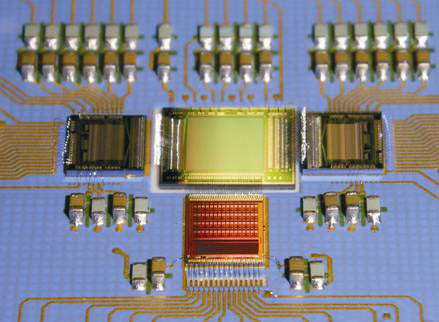
Photo of a 64 × 64 pixel DEPFET sensor prototype with readout and control front-end chips. |
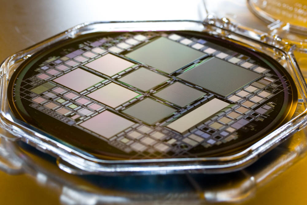
Photo of a 6-inch silicon wafer with DEPFET-APS prototypes for the WFI. |
Date: December 8, 2008
The international consortium developing Silicon Pore Optics is progressing well with the 2nd generation of these X-ray optics. On the 1st generation they had demonstrated the entire production chain, resulting in 17 arcsec HEW of mounted optics in flight configuration, tested with X-rays. The next milestone is to demonstrate less than 10 arcsec by 2009. For this they have just demonstrated stacks with Ir coating and carbon overcoat inside the pores and have upgraded the fully automated stacking robots with advanced plate cleaning systems. The required wedging techniques have been demonstrated to accommodate the shorter focal length of IXO. In depth environmental testing of the mounted optics is in preparation and shall take place late in 2009.
A mirror segment in the GSFC test facility
Date: November 17, 2008
The NASA IXO mirror technology team successfully completed another X-ray test of a recently fabricated mirror pair, achieving an image quality of 16 arcsec HPD and further demonstrating the validity of the suspension mount. They are also making rapid progress in transferring mirrors from temporary suspension mounts to a permanent structure simulating a module housing. Additionally, the team has bonded a mirror in another module housing simulator (the cube) and successfully vibro-acoustic tested it to appropriate launch levels.
In addition, a parallel effort has been underway to fabricate a pair of forming mandrels to meet the 5 arcsec IXO requirements. A pair of fused quartz mandrels have been refigured to better than 5 arcsec HPD, close to meeting 2 arcsec requirements need for forming mandrels.
Scanning electron micrograph of a cross section through a 574 nm-period CAT grating prototype.
Date: November 17, 2008
The Space Nanotechnology Laboratory at MIT´s Kavli Institute for Astrophysics and Space Research has recently demonstrated a new type of diffraction grating for high resolution soft X-ray spectroscopy that combines the traditional advantages of transmission gratings (low mass, relaxed alignment tolerances) and blazed reflection gratings (high broadband efficiency, use of higher orders for higher resolution). In addition, these so-called Critical-Angle Transmission (CAT) gratings become transparent at higher X-ray energies, which allows soft X-ray spectroscopy to be performed simultaneously with spectral imaging in the 1-10 keV band using other focal plane instruments, such as the X-ray Microcalorimeter System (XMS) or the Wide Field Imager (WFI), at the telescope focus. The CAT gratings were fabricated from silicon wafers using high precision interference lithography and advanced nano-fabrication techniques (http://snl.mit.edu/) and tested with X rays at the Advanced Light Source at Lawrence Berkeley National Lab, confirming their theoretically predicted behavior.
Additional Links
+ SPIE newsroom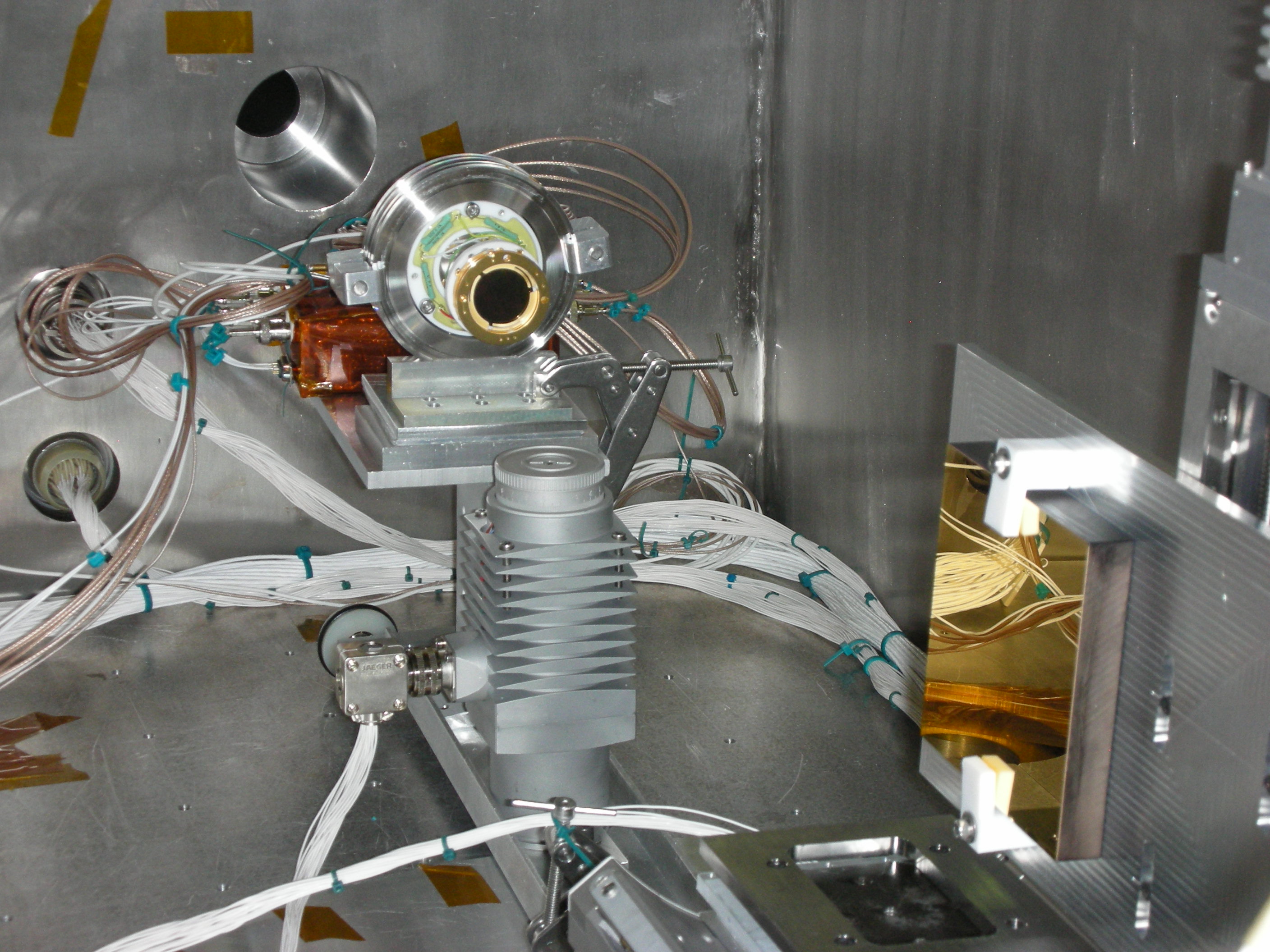
Grating test set-up at CU
Date: November 11, 2008
The gratings team, in the process of characterizing gratings for use in the off-plane X-ray Grating Spectrometer, have just completed efficiency testing the grating at the Gratings Test Facility at CU. The grating is a gold coated, radially grooved, type 4 holographic grating with 4500 grooves per mm. The grating itself is mounted on several linear and rotation stages allowing us to test different graze angles and incoming alpha angles. The grating is illuminated by a Manson Impact X-ray source at several energies of interest and the diffracted photons are observed via an MCP detector.
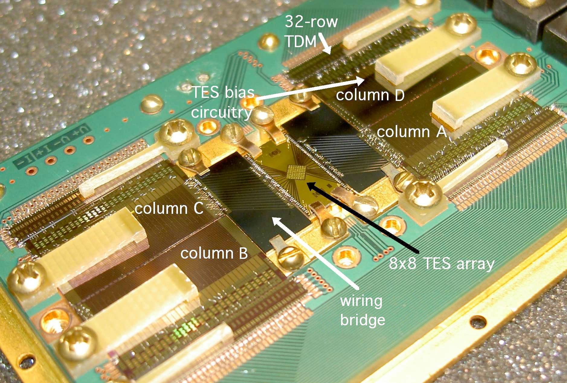
Photograph of a TES array and low-temperature read-out components. Click the image for larger view.
Date: Spring 2008
In the Spring of 2008, the Goddard Space Flight Center and National Institute of Standards and Technology collaboration used their state-of-the-art, time-division SQUID multiplexer system to demonstrate 2×8 multiplexing (16 pixels of a uniform 8x8 TES array read out with two signal channels) with modest degradation of the energy resolution. The average resolution for the 16 multiplexed pixels was 2.9 eV, and the distribution of resolution values had a relative standard deviation of 5%. Non-multiplexed, 2.3 eV resolution was obtained. The array was designed and fabricated at Goddard and the read-out system was designed and implemented at NIST.
 Top
Top
 Top
Top